

By Akram S. Alkhuzaie
Introduction:
Smart Transmitters are advancement over conventional analog transmitters. They contain microprocessors as an integral unit within the device. These devices have built-in diagnostic ability, greater accuracy (due to digital compensation of sensor nonlinearities), and the ability to communicate digitally with host devices for reporting of various process parameters.
The most common class of smart transmitters incorporates the HART protocol. HART, an acronym for Highway Addressable Remote Transmission, is an industry standard that defines the communications protocol between smart field devices and a control system that employs traditional 4-20 mA signal.
Parts of a Smart Transmitter:
To fully understand the main components of a smart transmitter, a simplified block diagram of the device is shown below:

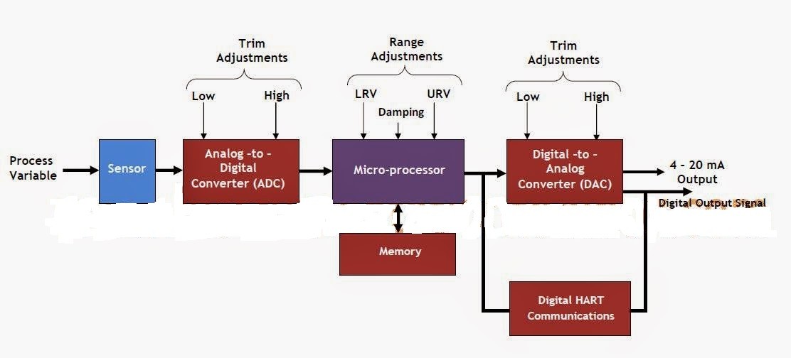
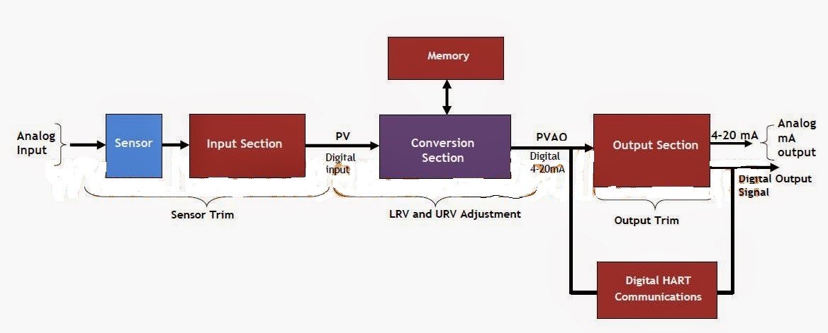
The above block diagram is further simplified to give the one below:

As shown above in fig A, the smart transmitter consists of the following basic parts:
(a) Process Sensor
(b) An Analog to Digital Converter(ADC)
(c) A Microprocessor
(d) A Digital to Analog Converter(DAC)
These basic parts can be organized into three basic sections as shown in fig B:
(a) Input Section
(b) Conversion Section
(c) Output Section
Input Section:
The input section comprises the process sensor or transducer and the Analog to Digital Converter (ADC). The sensor measures the process variable of interest (pressure, temperature, flow etc) which is then converted into a proportional electrical signal. The measured electrical signal is then transformed to a digital count by the Analog to Digital Converter (ADC). This digital count, representative of the process variable (PV), is then fed into the conversion section which contains the microprocessor.
However, the microprocessor must rely upon some form of equation or algorithm to relate the raw count value of the electrical measurement to the actual process variable (PV) of interest such as temperature, pressure, or flow. The principal form of this algorithm is usually established by the manufacturers of the smart transmitters, but most HART transmitters include commands to perform field adjustments. This type of adjustment is often referred to as a sensor trim. The output of the input section is a digital representation of the process variable (PV).
When you read the process variable using a hand held field communicator, this is the value that you see.
Conversion Section:
This section contains a microprocessor whose basic function is a mathematical conversion from the process variable to the equivalent mA representation of the process. closely connected to the microprocessor is the memory where the setup , configuration and diagnostic data of the transmitter are stored. The range values of the transmitter (related to the zero and span values) are used in conjunction with a transfer function to calculate this mA value. A linear transfer function is the most common, although pressure transmitters, may have a square root option. Still many other forms of transfer functions can be used with the processors or can be user defined. The output of the conversion section (PVAO) is a digital representation of the desired transmitter output. When you read the loop current using a hand held field communicator, this is the value that you see. Note that many HART transmitters support a command which puts the instrument into a fixed output test mode. This overrides the normal output of the conversion section and replaces it with a specified output value.
Output Section:
In this section, the calculated mA value representing the process variable is fed into a Digital to Analog Converter, where the mA value is converted into the actual analog 4 – 20mA electrical signal. Note once again that the microprocessor must rely on some internal calibration factors to get the correct value of this output. Adjusting these calibration factors is often referred to as a current loop trim or 4-20 mA trim.
As can be seen from the above discussion, the only similarity between the conventional analog transmitter and a smart transmitter is the process sensor that measures and converts the physical process variable into a corresponding electrical signal. Shown below is a simplified block diagram of a conventional analog transmitter:

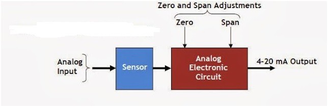
Instead of a purely mechanical or electrical path between the input and the resulting 4-20 mA output signal as obtain in conventional analog transmitters, a smart transmitter using the HART protocol has a microprocessor that manipulates the process data.
Based on the analysis above, it should be clear that the calibration procedure for a conventional analog transmitter is very different from that of a smart HART transmitter. While Zero and Span calibration is sufficient to make the analog transmitter perform within the manufacturer’s stated specifications; that of smart transmitters involve the calibration of either the input or output sections or both depending on the application. Zero and Span calibration for a smart transmitter is insufficient to make the device work within the stated performance accuracy documented by the manufacturers.
How to Calibrate Smart Transmitters
The procedure for calibrating a smart digital transmitter is known as Digital trimming. A digital trim is a calibration exercise that allows the user to correct the transmitter’s digital signal to match plant standard or compensate for installation effects. Digital trim in a smart transmitter can be done in two ways:
(a) A Sensor Trim: It consist of matching the process variable (be it pressure, level, flow or temperature) reading of the transmitter to a precision input. This process normally involves trimming the digital circuit of the input Analog-to-Digital converter in the smart transmitter.
(b) A 4 – 20mA or Current Loop Trim: This is done by trimming the output Digital-to-Analog converter in the transmitter.
Procedure for Calibrating a Smart Transmitter:
To do a proper calibration on a smart transmitter will involve both a sensor trim and/or a 4 – 20m A trim depending on the application where the transmitter is being used. A smart transmitter typically has high and low trim functions which unlike the zero and span adjustments of an analog transmitter, are non-interactive. That is adjusting the high trim function has no effect on the low trim function and vice versa.
Before proceeding to the section below note that a smart transmitter has three outputs which must be clearly understood:
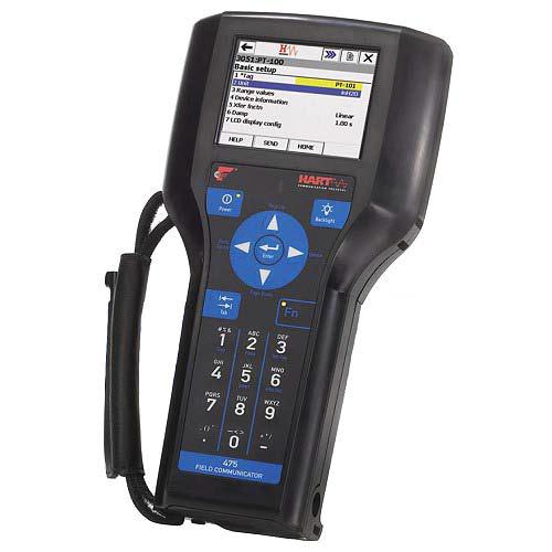
(a) Digital Process Variable (PV) usually read by a hand-held communicator
(b) Digital Value of the output current in mA (PVAO) which the communicator also reads.
(c) The analog 4 – 20mA signal output which can be read with a suitable milliammeter but cannot be read by the digital hand-held communicator.
For the smart transmitter to be properly calibrated, the error between the applied input to the transmitter and the digital output (PV) must be within the error specification of the manufacturer otherwise a sensor trim will be required to correct this. Similarly, the error between the digital milliamp value (PVAO) and the analog mA value must be within the error specification of the manufacturer otherwise a 4 – 20m A trim is required.
Performing a Sensor Trim:
Before performing a sensor trim, run a test, commonly referred to as the AS-FOUND TEST to confirm the consistency of the sensor and the input Analog-to-Digital converter. Connect the test setup as shown below:

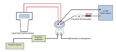
Use a precision calibrator to measure the applied input to the transmitter. Read the resulting output (PV) with a hand-held communicator. Calculate the resulting error between the applied input and the output (PV) since both are in the same engineering units. Note that the desired accuracy for this test will be the manufacturer’s accuracy specification. If this test does not pass, then follow the manufacturer’s recommended procedure for trimming the sensor. Below are general guidelines for performing a sensor trim:
(a) Apply the lower-range value stimulus to the transmitter, wait for it to stabilize
(b) Execute the “low” sensor trim function
(c) Apply the upper-range value stimulus to the transmitter, wait for it to stabilize
(d) Execute the “high” sensor trim function
Stimulus as used here should be understood to mean the process variable input to the transmitter.
Performing a 4 – 20mA Trim:
Before performing a 4 – 20mA trim, run a test, commonly referred to as the AS-FOUND TEST to confirm the consistency of the output Digital-to-Analog converter and the analog output of the transmitter. This procedure may also be called a 4-20 mA trim, a current loop trim, or a Digital-to-Analog converter trim. Connect the test setup as shown below:

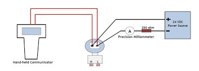
Use a hand-held digital communicator to put the smart transmitter into a fixed current output mode. The input value for this test is the mA value that you instruct the transmitter to produce. The output value is obtained using a precision milliammeter to measure the resulting current. Calculate the error between the digital mA value produced by the transmitter and the analog mA value measured by the current meter. The desired accuracy for this test should also reflect the manufacturer’s accuracy specification. If the test does not pass, then follow the manufacturer’s recommended procedure for trimming the output section. The trim procedure should require two trim points close to or just outside of 4mA and 20 mA. Do not confuse this with any form of re-ranging or any procedure that involves using zero and span buttons on the transmitter. Below are the general guidelines for performing a 4 – 20mA trim:
(a) Execute the “low” output trim test function on the transmitter.
(b) Measure the output signal with a precision milliammeter, noting the value after it stabilizes
(c) Enter this measured current value when prompted by the transmitter
(d) Execute the “high” output trim test function
(e) Measure the output signal with a precision milliammeter, noting the value after it stabilizes
(f) Enter this measured current value when prompted by the transmitter
After both the input and output (ADC and DAC) of a smart transmitter have been trimmed (i.e. calibrated against standard references known to be accurate), the lower- and upper-range values (LRV and URV) may be set. In fact, once the trim procedures are complete, the transmitter may be ranged and ranged again as many times as desired. The only reason for re-trimming a smart transmitter is to ensure accuracy over long periods of time where the sensor and/or the converter circuitry may have drifted out of acceptable limits. The situation is very different in an analog transmitter, where re-ranging necessitates re-calibration.

Many HART transmitters support a parameter called damping. If this is not set to zero, it can have an adverse effect on tests and adjustments. Damping induces a delay between a change in the transmitter input and the detection of that change in the digital value for the transmitter input reading and the corresponding output value. It is advisable to adjust the transmitter’s damping value to zero prior to performing tests or adjustments. After calibration, be sure to return the damping constant to its required value.
HART Communication Protocol :
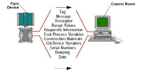
HART is an acronym for “Highway Addressable Remote Transmission”. The HART protocol makes use of the Bell 202 Frequency Shift Keying (FSK) standard to superimpose digital communication signals at a low level on top of the 4-2OmA. This enables two-way field communication to take place and makes it possible for additional information beyond just the normal process variable to be communicated to/from a smart field instrument.
The HART protocol communicates at 1200 bps without interrupting the 4-2OmA signal and allows a host application (master) to get two or more digital updates per second from a field device. As the digital FSK signal is phase continuous, there is no interference with the 4- 2OrnA signal.
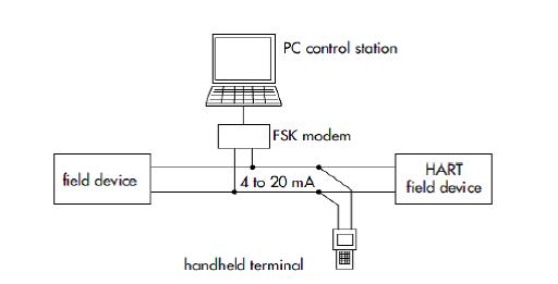
HART is a master/slave protocol which means that a field (slave) device only speaks when spoken to by a master. Master devices include handheld terminals as well as PC-based work places, e.g. in the control room. HART slave devices, on the other hand, include sensors, transmitters and various actuators. The variety ranges from two-wire and four-wire devices to intrinsically safe versions for use in hazardous environments. The HART data is superimposed on the 4 to 20 mA signal via a FSK modem. This enables the devices to communicate digitally using the HART protocol, while analog signal transmission takes place at the same time (see .Coding.on page 16ff and Lit./2/).Field devices and compact handheld terminals have an integrated FSK modem, whereas PC stations have a serial interface to connect the modem externally.
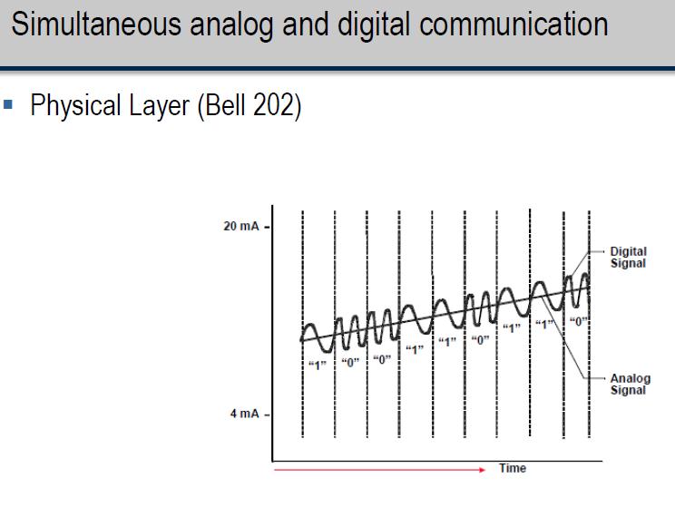

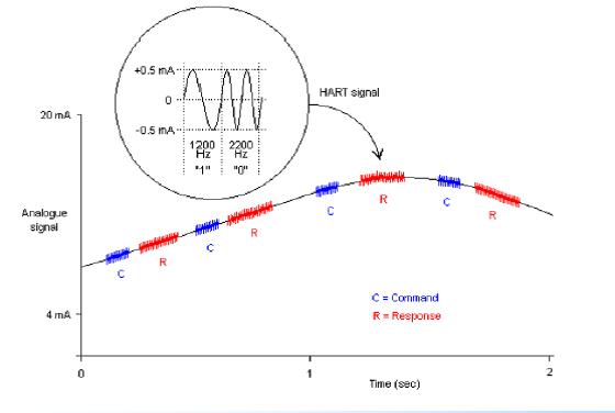

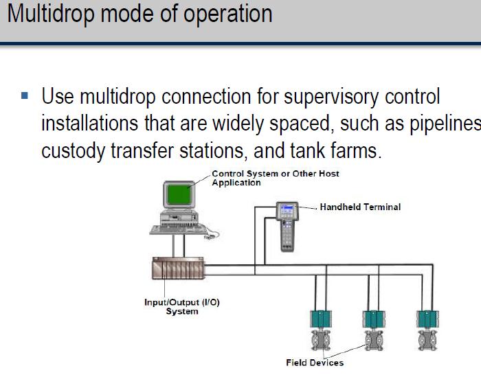
Figure below shows a typical connection scheme of a HART host device and a HART field device. HART communication is often used for such simple point-to-point connections. The HART protocol can be used in various modes for communicating information to/from smart field instruments and central control or monitor systems. HART provides for up to two masters (primary and secondary). This allows secondary masters such as handheld communicators to be used without interfering with communications to/from the primary master, i.e. control/monitoring system. The most commonly employed HART communication mode is master/slave communication of digital information simultaneous with transmission of the 4- 2O mA signal. The HART protocol permits all digital communication with field devices in either point-to-point or multidrop network configuration.
There is an optional “burst” communication mode where single slave device can continuously broadcast a standard HART reply message.


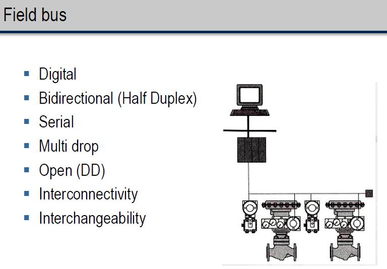

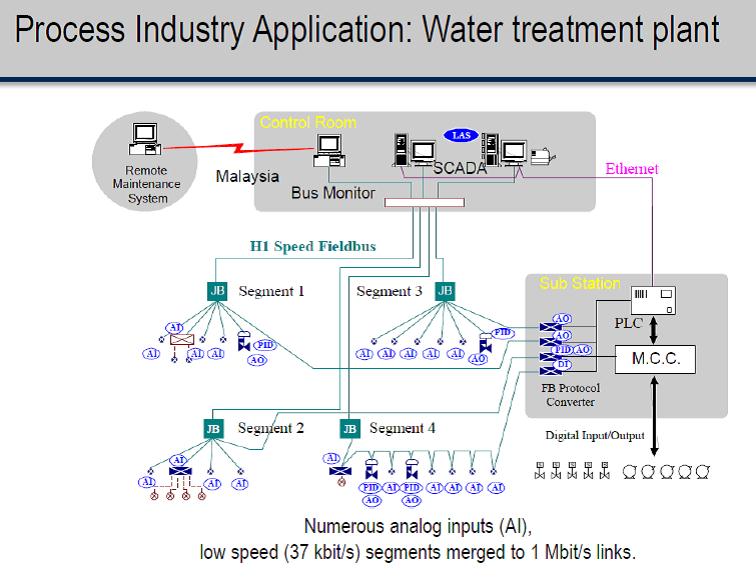
Field bus is A control network used in process control and industrial automation. Field buses are bi-directional, digital serial networks .Examples of fieldbus networks are FOUNDATION fieldbus, DeviceNet, ControlNet, Modbus and PROFIBUS. In the 1980s, field buses began to replace the parallel wiring used in 4-20 mA and +/-10 volt analog interfaces.