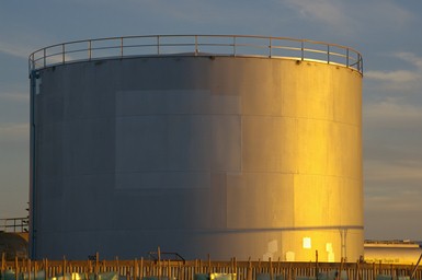
Tank Types
Tanks are usually described according to their function or their construction.
Their function may be receiving, settling, treating, dehydrating, washing, desalinating, storing or exporting. The construction is limited to two main categories:
a. Fixed-roof-tanks
b. Floating-roof tanks.
a) Fixed-Roof Tanks
see our Storage Tanks Books section
As the name implies, fixed-roof tanks are tanks which have their cylindrical shell covered by a roof that is an integral part of the tank construction. The roof plates rest on a supporting framework and are attached to the tank only at the top of the shell. A typical fixed-roof tank is shown in Figure below:
There are three types of fixed-roof tanks:
a. Non-pressure tanks which are in open connection with the atmosphere by vents installed in the roof.
b. Low-pressure tanks where instead of vents, pressure valves have been installed which open at pressures of 20 mbar over and 6 mbar under atmospheric pressure.
c. High- pressure tanks on which pressure valves open at design pressures of 50 mbar over and 6 mbar under atmospheric pressure.
Fixed-roof tanks are relatively easy to construct and therefore cheaper to build than floating-roof tanks. The main disadvantage of a fixed-roof tank is product losses due to the escape of vapour from the free space between the oil and the roof through vent openings in the roof. These losses are either breathing losses, caused by the difference in day and night temperature, or filling losses, when in flowing oil expels an equal volume of vapour through the vents.
Pressure Vacuum Valves
An alternative for reducing breathing losses is the installation of pressure/vacuum valves in the roof. These valves will not open before a certain overpressure or vacuum inside the tank is exceeded.
Pressure/vacuum valves are applied in two low/high settings:
a. Fully open at an overpressure of 20 mbar or a vacuum of 6 mbar. Tanks in which they are installed are called low-pressure tanks.
b. Fully open at an overpressure of 56 mbar or a vacuum of 6 mbar. Tanks in which they are installed are called high-pressure tanks.
Dome Roof Tanks are low pressure tanks with rounded tops. These tanks store highly volatile products at low pressures. Dome tanks isolate LPG and other products from the atmosphere. Dome tanks have special seals, relief valves, and vapor recovery systems. The relief valves send vapors to a flare if necessary. Vapor recovery systems condense vapors back into liquids and send them back into the tank.
Some dome tanks have single walls. Some dome tanks have double walls to insulate the tanks from the sun. LPG dome tanks have polyurethane, fiberglass, and foam glass insulation to keep the LPG cool. LPG dome tanks also have heaters under the floor to prevent the foundation from icing.
Refrigerated Storage Tanks
Refrigerated storage tanks store liquefied hydrocarbon gases like propane and butane. These tanks are usually large dome-roof tanks that are insulated to keep the stored product cool. The dome is designed to accommodate the positive pressure in the tank. Keeping the product cool allows it to be stored at or near atmospheric pressure. This makes the tank less expensive to build. Tanks are also provided with vacuum relief valves to protect (the tanks) against vacuum during product withdrawal.
A refrigerated tank receives liquefied gas from a gas plant refrigeration unit. These units compress and cool gas products to convert them to a liquid. This liquid is called rundown, or rundown product. Rundown is pumped from a refrigeration unit to a refrigerated storage tank.
Refrigerated storage tanks normally use autorefrigeration to keep the liquid product in the tank cool. Autorefrigeration is the process of cooling a liquid by allowing. some of the product to vaporise inside the tank. As the product vaporises, it absorbs heat from its surroundings. This cools the remaining liquid in the tank.
The vapor produced during autorefrigeration must be removed from the tank. Removing the vapor prevents pressure buildup inside the tank. Removing the vapor also allows the autorefrigeration process to continue. The removed vapor goes from the tank to a tank vapor recovery (TVR) system.
TVR systems use compressors, condensers, and flash drums to change the auto-refrigeration vapors back into liquid. This liquid is then returned to the tank as product. Tank vapor recovery systems increase the amount of product that a plant can produce.
Refrigerated storage tanks use mixing pumps to recirculate the product in the tank. These pumps take suction from’ the tank and discharge product back into the tank. Recirculating flow using mixing pumps keeps the product in tank at a constant temperature. In LPG tanks, mixing pumps help prevent LPG from separating into different products.
Pressurized Storage Tanks
Pressurized storage tanks are designed to store products under pressure. These tanks are normally classified as low-pressure, medium-pressure or high pressure tanks.
b) Floating-Roof Tanks
A floating roof-tank is open at the top. The roof itself is a steel disc which floats on the surface of the oil and rises or falls with the oil level as the tank is filled or emptied.
For a floating-roof tank, construction tolerances are rather small due to the fact that the roof must be free to move over most of the height of the tank. For this reason the permitted ovality is limited by the necessary clearance between the roof and the shell and this narrow tolerance increases the construction costs considerably. The higher construction costs of a floating-roof tank is outweighed by the advantages, which are:
a. Reduced product loss due to minimized vapour loss
b. Reduced air pollution for the same reason
c. Reduce fire and explosion risk due to very small vapour space.
Floating Roofs
The evaporation losses inherent with fixed-roof tanks can be almost entirely eliminated by the use of floating roofs. Floating roofs are designed to float on oil with specific gravities that vary from 0.7 to 1.0. They rise or fall with the oil level. In the design of a floating-roof two loading possibilities have been considered:
a. Oil leakage of the roof
b. Rainwater accumulation on the roof
It should be noted that floating roofs are not designed for a combination of leakage and rainwater accumulation. This means that the operator must avoid rainwater accumulation if the roof has any leaking pontoons.
Floating-roofs are completely welded structures, which are fabricated on site.
The following types can be distinguished:
a. Pontoon roofs
b. Double deck roofs Pontoon Roofs
In most cases the pontoon-type roof is used. The centre deck, made up of 5 mm thick lap-welded plates, is welded to the inner side of the annular pontoon, which provides the buoyancy.
The surface of the pontoon is 20-25% of the total roof surface. The pontoon is built of compartments which are separated from each other by liquid tight bulkheads. This ensures that a leakage in one of the compartments will be limited to that particular compartment.
For large diameter tanks, e-g- over 50 metres, special types of floating-roofs are sometimes used. In the Shell Group a number of SIPM-type floating-roofs are in service.
Double-Deck Roofs
In a number of cases double-deck roofs (double-deck over the whole liquid surface) are used instead of pontoon roofs. For this type of roof the lower deck rests on the liquid and some distance above this, the upper deck rests on the lower deck, supported by bulkheads and supporting, concentric rings.
The air space between the two decks provide an effective insulation against solar radiation. The upper deck has a slight incline towards the centre of the roof. For very large roofs even a double incline may be used.
Apart from the advantage of the insulating effect mentioned above, there are a number of occasions when a double deck roof instead of a pontoon roof may be chosen:
a. For small diameter tanks, up to 15 metres, because with these small diameters the centre deck of a pontoon roof would be too small to produce the diaphragm effect
b. For large and very large diameter tanks, over 60 metres, located in areas with very strong winds. Strong winds may cause fatigue cracks in the single, centre decks of large pontoon roofs, resulting in oil seepage onto the centre deck.
Roof Drains
Drainage of rainwater is important for the trouble-free operation of a floating-roof tank. Any rain falling on the roof is collected in a sump at the lowest point of the roof. It is discharged via an articulated steel drain pipe (sometimes through a flexible hose drain) installed between the sum and a nozzle in the lowest course of the shell. A check valve is installed near the roof end of the pipe to prevent back-flow of stored product in case of leakage of the pipe drain or its swing Joints. A gate valve, ‘ust outside the tank shell, permits the drainage system to be closed off. However, considerable care should be taken to ensure the roof drainage system is not inadvertently left closed.
Pontoon-type roofs are designed to carry 250 mm of rain on the centre deck in a floating condition. This accumulation of rainwater could arise for example when the roof drain is plugged. Emergency drains, discharging into the oil storage cannot be applied, since the level of the oil will always be higher than the level of the rainwater on the centre deck (see Figure 9). This means that the operator in charge has to be particularly alert during periods of heavy rain to ensure the water is drained, thus preventing the floating roof from collapsing or even sinking when the rainwater load on the centre deck reaches the design average of 250 mm rainfall.
Double-deck roofs are provided with emergency drains to limit the rainwater load to a value which will be carried safely. This is possible because the oil level in the tank will always be lower than the rainwater level on the deck. The rainwater will be discharged into the product when it reaches the overflow level of the emergency drains.
Floating Suctions
Storage tanks in production areas often act as settling tanks, and as a result, crude with a high water content, free water and sludge are likely to be present in the bottom layers. In general, floating-roof tanks are emptied via an outlet approximately 30 cm above the bottom of the tank. Crude that is drawn through such an outlet from the tank could therefore be severely contaminated. In a floating-roof tank this is prevented, or at least significantly reduced, by the use of a floating suction.
This is a movable pipe that connects the outlet nozzle of the shell with a guide structure underneath the centre deck of the floating roof. See Figure 14. The upper intake end of the suction pipe is normally pressed against the roof by a float attached to it. The guide structure at the underside of the roof ensures the horizontal movement of the upper end of the pipe when the floating roof is moved up and down.
To eliminate the need for a guide structure, the floating suction pipe may be articulated and connected to the roof as an articulated roof drain.
Roof Access Ladders
For inspection and maintenance purposes an access ladder is provided from the top of the shell to the roof, running over a rail track on the roof. Often these ladders are provided with self-levelling stair treads, which are always in a horizontal position. For such a ladder there must be sufficient space to move up and down inside the tank. As a consequence the height of small-diameter tanks must always be less than the diameter. In marketing depots, where generally small-diameter floating-roof tanks are used, this problem is overcome by installing the rails on which the ladder rolls on an elevated structure on the centre deck. So the height of the ladder (or the height of the tank) is artificially reduced.
Roof Supports
The floating roof is provided with roof supports, which can be adjusted to two positions. The first position is approximately 0.9 m above the tank bottom to keep the roof free from all accessories on the tank bottom. The second position is approximately 1.8 m above the tank bottom for access under the roof during maintenance.
References:
1. Storage Tanks - Gap Elimination Program.
2. Design, Construction and Operation of Floating Roof tanks.